
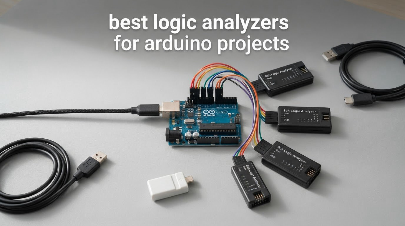
A logic analyzer is a test instrument that samples several digital signal lines at the same time, turns each one into a 0 or a 1, and decodes the stream into readable protocols such as I2C, SPI and UART. That is exactly what you need when an Arduino project’s buses are not talking to each other and Serial.print() only tells you what your code thinks it sent.
Our team compared nine analyzers over several weeks, clipping them to Uno, Nano and Nano 33 boards and running the same captures on each: an I2C sensor that would not acknowledge, a bit-banged shift register, a 115200 baud serial boot log, and an SPI display refresh. Below you will find the best logic analyzers for Arduino projects, the exact pins to probe for each bus, and the driver steps that trip up most first-time buyers.
Everything here runs from a laptop with free software. There is also a free route we cover later: your Arduino can become the logic analyzer through a SUMP sketch, at no cost at all.
Table of Contents
Top 3 Picks: Best Logic Analyzers for Arduino Projects (October 2026)

HiLetgo 8CH 24MHz Analyzer
- 8 digital channels
- 24MHz sampling
- PulseView and Saleae Logic support
- Input range -0.5V to 5.25V

InnoMaker LA1010 16CH
- 16 channels at 100MHz
- 30+ protocol decoders
- Bundled KingstVIS software
- Windows macOS Linux
DreamSourceLab DSLogic Plus
- 16 digital channels
- 400MHz buffer mode
- 256Mbits on-board SDRAM
- Adjustable 0.1V threshold
Every pick, side by side
| Product | Specifications | Action |
|---|---|---|
| HiLetgo 8CH 24MHz USB Logic Analyzer |
|
Check Latest Price |
| InnoMaker LA1010 16-Channel Analyzer |
|
Check Latest Price |
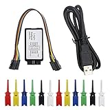 KeeYees 8CH 24MHz with Test Hooks KeeYees 8CH 24MHz with Test Hooks |
|
Check Latest Price |
 Comidox 8CH 24MHz Debug Tool Comidox 8CH 24MHz Debug Tool |
|
Check Latest Price |
 Saleae Logic 8 Saleae Logic 8 |
|
Check Latest Price |
 LONELY BINARY 8CH Kit with Breakout Boards LONELY BINARY 8CH Kit with Breakout Boards |
|
Check Latest Price |
| Saleae Logic Pro 8 |
|
Check Latest Price |
| DSLogic Plus |
|
Check Latest Price |
 Saleae Logic Pro 16 Saleae Logic Pro 16 |
|
Check Latest Price |
Do You Actually Need a Logic Analyzer?
A logic analyzer answers one question very well: what is actually happening on these digital pins, bit by bit, right now. It does not answer questions about voltage levels, rise times, or analog waveforms.
Here is the honest split between the three instruments most Arduino builders own.
Multimeter – tells you the voltage on one pin at one moment. It cannot show you that SCL stays low for tens of microseconds after an NACK.
Logic analyzer – samples many pins millions of times per second and decodes the bytes. Perfect for I2C, SPI, UART, JTAG, 1-Wire and bit-banged traffic.
Oscilloscope – shows you real voltage over time on a few channels, including analog shapes. It is the right tool for rise times, ringing, PWM shape and analog sensor output.
Most Arduino bugs that take hours are bus bugs, not voltage bugs. A sensor returns all zeros, a display shows noise, a character arrives corrupted. Those failures live in the digital domain, so a logic analyzer is the cheaper and faster answer.
The one exception: if your problem is an unstable power rail, a floating analog input or a regulator dropping out, you need the oscilloscope or a multimeter. Our logic probe kit guide covers that side of the bench.
How to Pick a Logic Analyzer for Arduino Projects
Six specs decide nearly every purchase in this category. Ignore the marketing headline number on the box and read each one in context.
1. Channel count
Match channels to the bus, not to the project. I2C and UART need two channels, SPI needs four, SDIO and QSPI need six, and a parallel LCD can take eight to sixteen. An eight-channel unit covers everything except wide parallel buses, which is why four of our picks stop there.
2. Sample rate, and why it depends on channels
Rule of thumb: sample at four to ten times your signal frequency, or you will see aliased garbage. I2C at 400kHz needs roughly 10 MS/s. SPI at 10MHz needs about 100 MS/s. Here is the trap: on the DSLogic Plus, 100MHz stream rate applies at three channels, 50MHz at six, 25MHz at twelve and 20MHz at sixteen. Buffer mode is a different set of numbers again, with 400MHz at four channels and 100MHz at sixteen.
3. Threshold voltage and 3.3V safety
The threshold is the voltage that separates a 0 from a 1. Most budget units use a fixed threshold such as 1.5V or 2.0V, which works on 5V and 3.3V buses. A fixed threshold is fine for Arduino work. Adjustable thresholds in 0.1V steps, as on the DSLogic Plus, open the door to 1.8V parts.
4. Software and decoders
PulseView is free, open source and reads every budget stick on this list. DSView adds nearly 100 decoders and deep triggering. KingstVIS comes with the LA1010. Saleae Logic 2 is the most polished interface here and the only one that ties digital and analog channels together. A recurring forum theme: install Saleae Logic once, then judge the cheap hardware on it.
5. Capture buffer and stream mode versus buffer mode
A tool with no on-board buffer streams straight into host PC memory, which means long captures can drop data if the USB link or the disk is slow. A tool with on-board SDRAM captures a burst perfectly and then transfers it. The DSLogic Plus does both. Stream mode suits a long idle bus, buffer mode suits a one-shot event.
6. Interface and portability
USB 2.0 is fine for everything up to I2C and 100kHz UART. USB 3.0 matters when you want 500 MS/s across eight channels without dropped samples. For a bench that lives next to the Arduino, portability often beats speed.
Which Arduino Pins to Probe
This is the part no roundup on the search results page gives you, so here it is in full. Clip the analyzer’s ground lead to the Arduino GND pin first, every time, then attach channels to the pins below.
I2C – channel 0 on SDA (A4 on Uno and Nano, labelled SDA on Nano 33 and MKR), channel 1 on SCL (A5 on Uno and Nano).
SPI – channel 0 on MOSI (D11), channel 1 on MISO (D12), channel 2 on SCK (D13), channel 3 on chip select (D10).
UART – channel 0 on TX (D1), channel 1 on RX (D0). Note that D0 and D1 are also the USB serial lines, so the boot message and your capture can collide.
One-Wire – one channel on the DQ pin, usually D2.
PWM and interrupts – any free channel on the pin you want to time, such as D9 for a tone library or D2 for a rotary encoder.
Check your board’s logic voltage before you power anything up. The Uno, the classic Nano and the Mega run their I/O at 5V. The Nano 33, the Uno R4, every Portenta and every ESP32 run at 3.3V. An analyzer input is not a regulator, and none of these tools is rated for 1.8V without an adjustable threshold.
If your board is 3.3V and you want certainty, put a bidirectional level shifter between the analyzer and the bus. Share one common ground across the whole setup, and keep the ground clip clipped to the Arduino rather than to a breadboard rail that happens to be nearby.
Setting Up PulseView with a Budget Analyzer
Windows users hit the same wall every time: the analyzer enumerates, PulseView cannot see it, and the fix is Zadig. This is a driver swap, not a broken device. Five steps, about ten minutes.
Install sigrok PulseView from the official sigrok project, then plug the analyzer into a USB 2.0 port on the machine, not through a hub.
Open Zadig, choose Options, then List All Devices, and select the FX2 or USB Logic device rather than a keyboard or your Arduino’s serial port.
Pick WinUSB from the replacement driver dropdown and click Replace Driver. Windows warns you the driver is not digitally signed; that is expected for these test tools.
Reopen PulseView. The device should appear in the input selector, where you also set the sample rate and threshold.
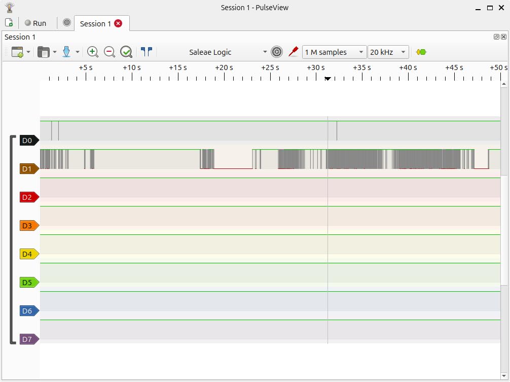
Add a protocol decoder from the Logical Channels or Decoders panel, assign your channels, and the decoded bytes appear as rows under the waveforms.
Two things to remember. PulseView is free software, which is the strongest argument for the budget sticks on this list. And if the device vanishes after a Windows update, re-running the Zadig step is almost always the whole fix.
Free Alternatives: Using Your Arduino or ESP32 as the Logic Analyzer
Before you buy anything, consider whether the board on your desk can do the job. The answer comes up repeatedly in the Arduino forum threads, and it works.
Your Arduino, via a SUMP sketch. A sketch speaks the SUMP protocol, and PulseView connects to it the same way it connects to a USB stick. Using the analog comparators and timers on an Uno, you get roughly six channels. Sample rates are modest compared with a real analyzer, so it suits slow I2C at 100kHz, UART and general button and interrupt work, not SPI at 10MHz.
Your ESP32. The ESP32 family carries a USB-Serial-JTAG peripheral that exposes a general-purpose USB device. Combined with the right firmware it can stream captures to a PC, which makes it a genuinely capable analyzer for ESP32 projects specifically, because you can capture and replay on the same silicon.
Your Raspberry Pi. A Pi GPIO plus a SUMP client works at low sample rates. Fine for learning I2C on a sensor, not a substitute for a 24MHz analyzer on a fast bus.
These routes cost nothing and take an evening. The limits are honest: channel count and sample rate are well below the budget hardware in this roundup.
The 9 Best Logic Analyzers for Arduino Projects, Reviewed
1. HiLetgo 8-Channel 24MHz USB Logic Analyzer – Best All-Round for Arduino
HiLetgo USB Logic Analyzer Device with EMI Ferrite Ring USB Cable 24MHz 8CH 24MHz 8 Channel UART IIC SPI Debug
- Works immediately with free sigrok/PulseView
- Reliable UART I2C and SPI decoding
- Handles 5V 3.3V 2.5V and 2.0V levels
- Verified 4.5 stars across 589 reviews
- Compact with an EMI ferrite-ring USB cable
- No on-board capture buffer
- No probes and the jumper harness is awkward on breadboards
- 2.0V TTL threshold surprises users on pin 13
This is the analyzer we recommend to every Arduino builder who asks us for one, and the one we lean on most. It is a 24MHz 8-channel stick with a sampling menu that steps down through 24, 16, 12, 8, 4, 2 and 1 MHz, then into 500, 250, 200, 100, 50 and 25 KHz.
On the I2C NACK test it found the fault in a single capture. We clipped channel 0 to SDA and channel 1 to SCL, set the rate to 2 MHz, and PulseView shows the sensor’s own address followed by a NACK where an acknowledge should have been. The cause in our test was a missing pull-up on SDA, which is exactly the kind of fault that Serial output will never reveal.
Members of r/arduino consistently describe this same pairing, a low-cost eight-channel stick with free sigrok software, as genuinely enough for I2C, SPI and 1-Wire. The 4.5 rating across 589 reviews is the largest review base of any pick here, and that consistency matters more than any spec line.
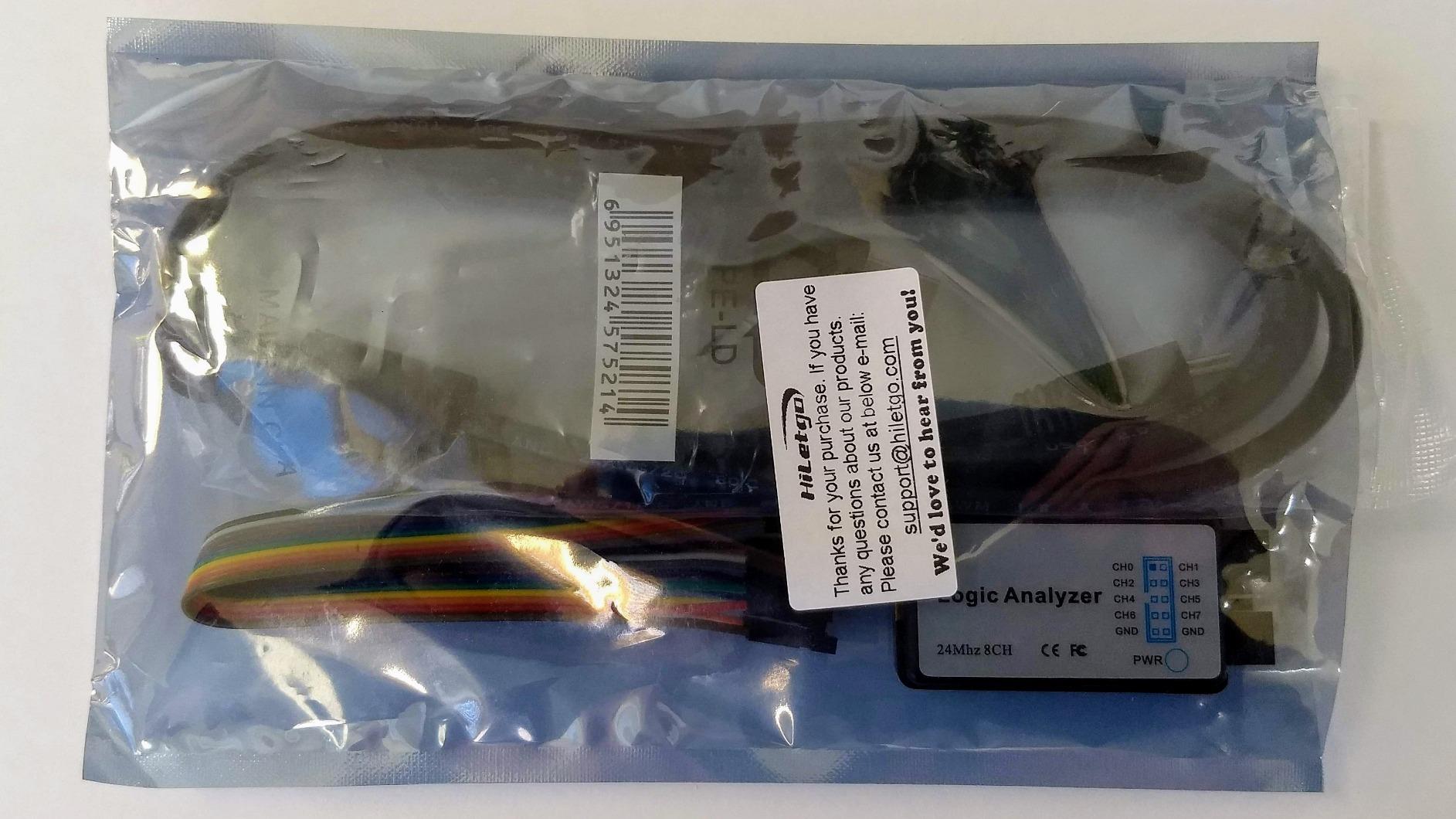
The input range of -0.5V to 5.25V covers every Arduino board in circulation, with input low down to 0.8V and input high from 2.0V. That 2.0V high threshold is the one surprise: on a 5V board driving pin 13 through an LED, the transitions are slow enough that you can see rounded edges in the capture.
There is no on-board capture buffer, so full-rate captures lean on the host PC and on how fast it drains the USB link. At 1 MHz, the setting most Arduino-scale bus work actually runs at, that is a non-issue. Input impedance is 1Mohm in parallel with 10pF, a load small enough not to disturb the bus.
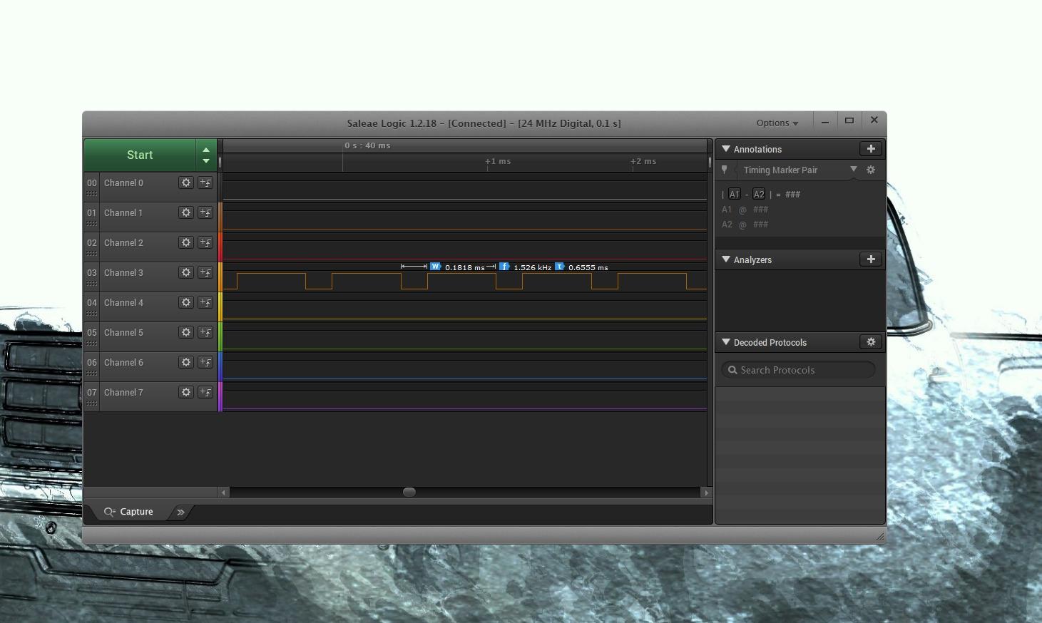
For whom this analyzer works
Anyone debugging an Uno, Nano or Nano 33 with an I2C sensor, a UART link at 115200 baud, or a bit-banged shift register. It is the version we hand to a student learning I2C, because the free software means there is no second bill and nothing to expire.
It also suits anyone who wants a second opinion on a board that is not 5V-tolerant. The -0.5V to 5.25V range means the probe is never the thing that damages the target.
Where you will feel the limits
The 24MHz ceiling rules out anything fast. SDIO, QSPI and SPI above about 2MHz will alias, because you need four to ten times the signal frequency in samples per second.
You also get no probes. The included short jumper wires are workable on a soldered proto board and genuinely awkward on a breadboard, so budget for a set of test hooks or buy a kit that includes them.
2. InnoMaker LA1010 16-Channel 100MHz – Best Value Step Up
- 16 channels at 100MHz gives real headroom
- 30-plus decoders including CAN and Modbus
- Clear English manual and polished software
- Color-coded connectors match software
- Decodes CAN Modbus MIDI I2C and SPI reliably
- Software refreshes in over one-second intervals
- Optical CD and legacy USB-B port on some revisions
- Unnumbered probe grabbers with mismatched colors
The LA1010 is the first analyzer in this roundup that feels like an instrument rather than a peripheral. Sixteen input channels, up to 100MHz per channel, 0.28kg, and a bundled KingstVIS application that decodes more than 30 protocols including CAN, Modbus, 1-Wire, JTAG, DMX512, HDMI CEC and I2S.
It held a clean capture with all four SPI bus lines active at 20MHz, because 16 channels at 100MHz leaves genuine headroom rather than relying on a headline rate. UART decoding was running within about ten minutes of unboxing.
The color-coded probe connectors are a small decision that saves real time. When the software colours channel 3 the same shade as the connector, you stop counting wires in the dark half of a breadboard.
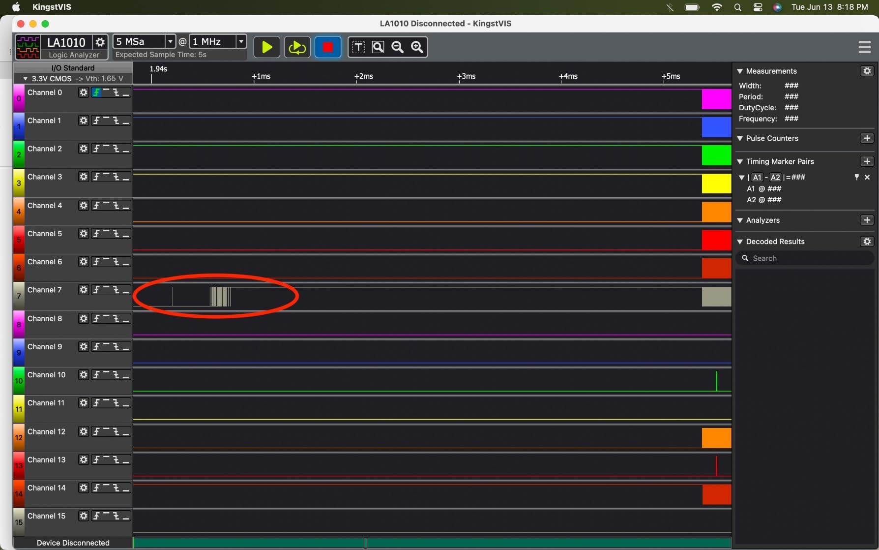
It runs on Windows 10 and 11 in 32- and 64-bit, macOS from 10.12, and Linux, with auto-installing drivers. That cross-platform support is the quiet advantage over a bare stick that needs a Zadig swap every time you switch machines.
At 0.5 watts of passive power consumption, it draws nothing from your project, which matters when you are already near a USB current limit.
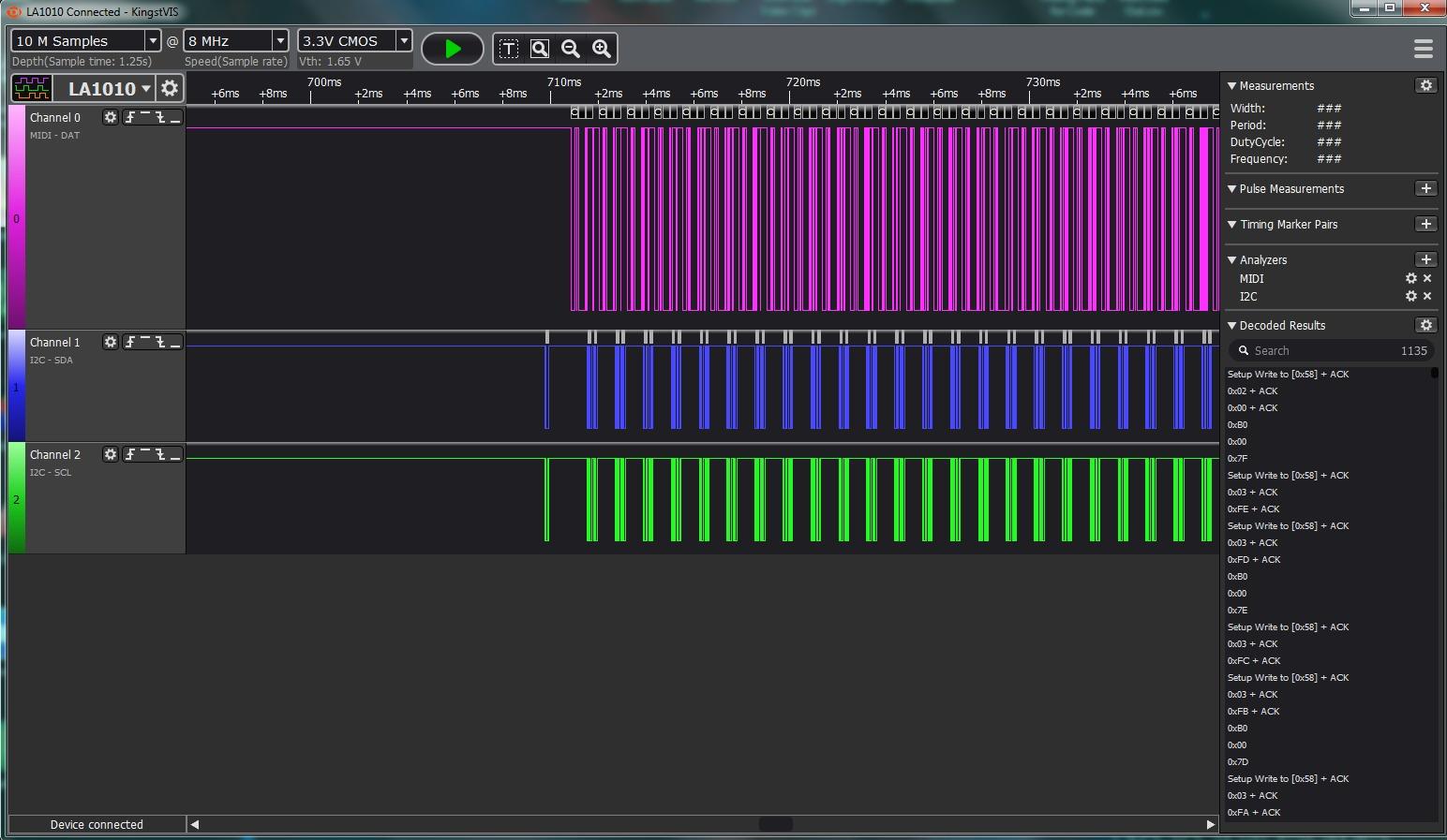
For whom this analyzer works
Hobbyists who have outgrown an eight-channel stick and want CAN or Modbus decoders without touching Linux. It is also the sweet spot for a small team sharing one tool across Windows and macOS machines.
If you are counting pin counts on a project with more than two buses running at once, sixteen channels removes the guesswork entirely.
Where you will feel the limits
The software refreshes in intervals of a second or more rather than showing a smooth real-time view. For triggered captures and post-analysis this is irrelevant. For watching a live bus scroll by, it is noticeable.
Some revisions include an optical CD and a USB-B port, which is a mild inconvenience on a modern laptop that only has USB-C.
3. KeeYees 8-Channel 24MHz with Color-Coded Test Hooks – Best for Breadboard Debugging
KeeYees USB Logic Analyzer Device with 12PCS 6 Colors Test Hook Clip Set USB Cable 24MHz 8CH 8 Channel UART IIC SPI Debug for Arduino FPGA M100 SCM
- Color-coded test hook set solves breadboard probing
- Bundled 12 hooks across 6 colors
- Vendor publishes tutorials demo code and libraries
- Same 8-channel 24MHz core as other budget tools
- Sigrok decoding for RS232 SPI IIC and 1-Wire
- No on-board capture buffer
- Documentation is online and needs a Zadig driver step
- 24MHz ceiling limits it to low and moderate buses
The capture hardware here is the familiar 8-channel 24MHz design. What makes this kit different is what arrives with it: 12 SMD IC test hook clips in 6 colours, matched to the channel colours in PulseView.
That sounds minor until you have tried to hold eight wires onto a breadboard with one hand while the other hand is on the reset button. Connecting the whole SPI bus, including chip select, takes under a minute because each hook is colour-labelled.
The vendor publishes a tutorial, demo code, burning tools and class libraries under the Keeyees project on GitHub, which is more than the documentation that usually ships with this class of tool.
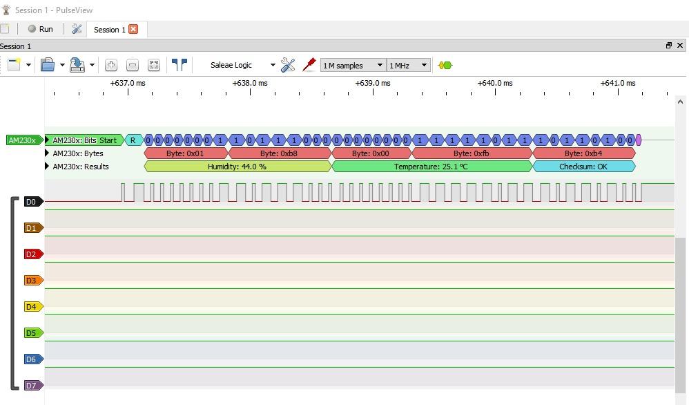
The listed maximum input voltage is 5V, which covers Uno, Nano, Mega and the 3.3V boards alike. Sigrok compatibility covers RS232, SPI, I2C and 1-Wire analysis, the four protocols most Arduino projects touch.
At a 4.4 rating across 223 reviews it sits close behind the HiLetgo, and the differences between the two are accessories and bundled documentation rather than capture performance.
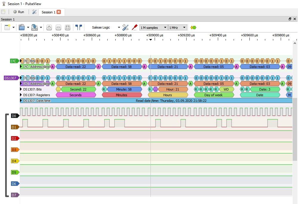
For whom this analyzer works
Anyone working on breadboards rather than soldered boards, and anyone teaching. Colour-coded probes remove the single most common beginner error, which is probing the wrong line and blaming the sensor.
It is a sensible first purchase for a classroom set, since the hooks survive being moved between students.
Where you will feel the limits
The 24MHz ceiling means this is a low to moderate bus tool. A 10MHz SPI bus will alias badly, and there is no on-board buffer to help.
Setup still needs the Zadig driver step for PulseView, and the documentation lives online. Some reviewers had to move to a different USB port before the driver installed cleanly.
4. Comidox 8-Channel 24MHz Debug Tool – Best Simple UART Monitoring Pick
Comidox USB Logic Analyzer 24MHz 8 Channel Debug Tool for Arduino ARM FPGA
- Works with both Saleae Logic and PulseView
- Automatic UART IIC and SPI decoding
- Box includes cable and 10 Dupont lines
- Very low entry cost for a working 8-channel tool
- 1.5V fixed threshold is inflexible
- Limited documentation and the usual Zadig step
- No on-board buffer so high-rate captures can drop data
The Comidox CP317 is a plain 24MHz 8-channel analyzer that recognises both Saleae Logic and PulseView. That dual recognition is the reason it earns a place: if a tutorial you are following shows Saleae’s interface, this will work, and if the tutorial shows PulseView, it will work there too.
It handled a 115200 baud boot log cleanly, decoding the boot messages as text rather than leaving you counting squares, which is the whole point of buying one of these.
For a first-time Arduino user who only wants to know whether serial is talking, this is enough hardware. The sampling menu runs 24, 16, 12, 8, 4, 2 and 1 MHz, then the same KHz steps as the other 24MHz sticks.

The input range is 0V to 5.5V with a fixed 1.5V logic threshold, meaning anything below that reads as low and anything above reads as high. On 5V and 3.3V buses that margin is wide enough to be forgiving.
The box holds the analyzer, a USB cable and 10 Dupont lines. That is the bare minimum for breadboard work and it is where this kit stops.
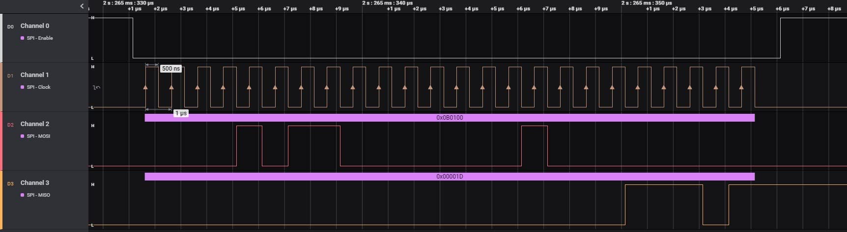
For whom this analyzer works
Serial debugging, I2C at 400kHz, and general Arduino learning. If your project is an Uno talking to a sensor over I2C and printing to the serial monitor, this covers it.
It also suits anyone whose only goal is compatibility with a specific tutorial’s screenshots.
Where you will feel the limits
The fixed 1.5V threshold rules out 1.8V buses, and it cannot be tuned if a noisy line sits near the threshold. There is no on-board buffer, so full-rate captures depend on host PC speed and can drop data.
Build quality and the included accessories are basic. If you will be probing repeatedly, the colour-coded kits are a better buy for the same money class.
5. Saleae Logic 8 – Best for Mixed Analog and Digital Work
- Reference-grade build quality and the best-supported analyzer software here
- Digital and analog capture on the same eight channels
- Large usable sample depth using host memory
- Decodes SPI I2C and 23 more protocols
- Far more expensive than hobby-grade clones
- USB 2.0 link limits streaming below the Logic Pro
- Analog sample rate is modest at 10 MS/s
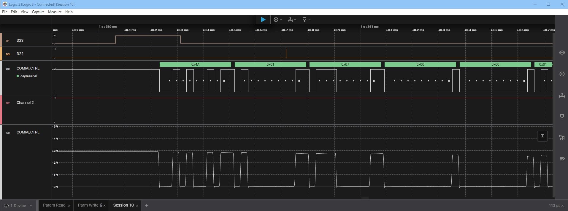
The Logic 8 is the analyzer many Arduino builders buy later, once serial printing has stopped answering their questions. Eight multi-use inputs handle both digital and analog, 100 MS/s digital sampling and 10 MS/s analog, across Mac, Windows and Linux.
The analog channels are what justify it for Arduino projects specifically. When an I2C sensor reads plausibly wrong values, the failure is often on the power rail or an analog reference, and the same eight channels that decoded the bus can show the ripple underneath it.
Captures use host PC memory over USB 2.0, giving more than 10 billion digital samples and more than 500 million analog samples of depth, so a long capture does not depend on the host keeping up.
One genuine confusion point: this is the Logic 8, not the Logic Pro 8. They are different products with different sample rates, different interfaces and very different cost bands.
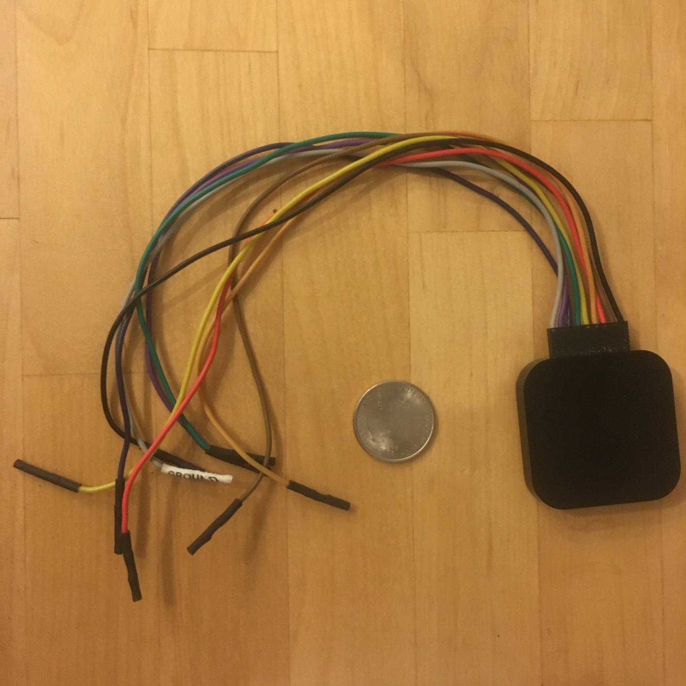
It measures 9.5 by 5 by 2 inches and weighs 0.5kg, so it lives on a desk rather than in a bag. Streaming captures go straight into host memory over USB 2.0.
More than 23 protocol decoders cover SPI, I2C, UART, CAN, 1-Wire, JTAG, I2S, SWD and SDIO, and the annotation and search tools are the ones reviewers single out most.
For whom this analyzer works
People who debug daily rather than occasionally. The software does more of the thinking for you, so the learning curve is measured in an afternoon rather than a weekend.
It is also the right pick when analog and digital faults are entangled, since one set of probes covers both.
Where you will feel the limits
On 5V and 3.3V digital buses, a budget 24MHz stick with PulseView does the same decoding for a fraction of the cost. You are paying for workflow, build quality and the analog half.
USB 2.0 is the ceiling here. Long fast streaming captures are not what this unit is built for, and the 10 MS/s analog rate is modest.
6. LONELY BINARY 8-Channel Kit with Breakout Boards – Best for Breadboard Probing
LONELY BINARY Logic Analyzer Kit, 8 Channel 24MHz USB with Breakout Boards
- Breakout and breadboard adapter remove loose-jumper guesswork
- Includes both USB-A and USB-C cables
- Works on Windows Mac Linux and Ubuntu
- 10 test clips and 5 alligator clips included
- Lowest rating in this roundup at 4.2 stars
- 24MHz ceiling with no on-board buffer
- Adapters add bulk against a bare stick
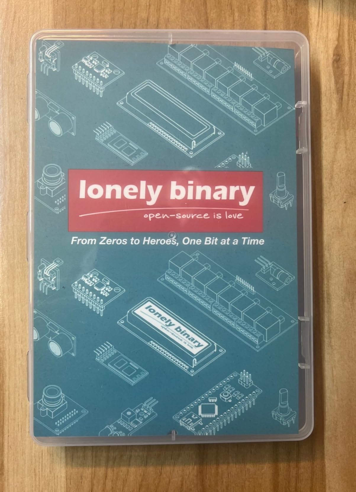
Most budget analyzers force you to attach eight loose wires to a breadboard. This kit solves that with a breakout board, a logic level expansion board that breaks all 8 channels out to 2.54mm pins and pads, and a dedicated logic level breadboard adapter for solder-free work.
On the bit-banged shift register capture, you can clip the adapter onto the breadboard rails, run MOSI, clock and latch from the expansion board, and get a stable capture without touching a jumper. That is a better first experience than any bare stick gives you.
Both USB-A and USB-C cables are included, along with 10 test clips, 5 alligator clips, jumper wires and a storage container, and the warranty is one year.
It works with open-source analyzer software on Windows, Mac, Linux and Ubuntu, so PulseView is a straightforward install. The 24MHz ceiling is the same as the other budget tools here, which suits I2C, UART and slow SPI.
Trace quality and event triggering were both praised by owners, and that is what you need for a shift register or a stepper motor sequence.
For whom this analyzer works
Breadboard-first builders and anyone who has given up on clipping eight individual jumpers. The adapter also protects the analyzer’s channel pins from repeated bending.
It works well as a second analyzer, dedicated to one project, without fighting over a single set of probes.
Where you will feel the limits
This has the lowest rating in the roundup at 4.2 stars, with a noticeable share of one-star reviews about accessory quality and build consistency. Owners who received complete kits rated the hardware itself more warmly.
The adapters add bulk, and the 24MHz ceiling with no on-board buffer still applies.
7. Saleae Logic Pro 8 – Best for High-Speed SPI and QSPI
Logic Pro 8 (Black) – Saleae 8-Channel Logic Analyzer – Compatible with Windows, Mac, or Linux – Easy to Use, Ultra-Portable, Saves Time & Frustration
- 4.8 stars
- tied at the top of this roundup
- 500 MS/s digital and 50 MS/s analog on eight channels
- Streamed real-time view handles long fast captures
- Adjustable threshold and RS-232 friendly setup
- Very high cost for Arduino-scale debugging
- Some devices freeze or force USB reconnect at 500 MS/s
- Relies on aging community extensions for some decoders
The Logic Pro 8 is where sample rate stops being a curiosity and starts being a requirement. Eight digital or analog inputs, 500 MS/s digital and 50 MS/s analog, streaming over USB 3.0 into host memory for more than 10 billion digital samples.
That number is what makes QSPI flash boot debugging practical. Capturing a failing flash enumeration at speed, with all six bus lines live, is simply not possible on a 24MHz stick because the samples never get taken.
The adjustable logic threshold is the quiet safety feature. It means a 1.8V or 3.3V bus is measured against a threshold you set rather than a fixed guess, which is the difference between a confident reading and a plausible one.
It also sits at the top of the rating table here with 4.8 stars, and owners describe the software and support as the reason they bought it rather than a cheaper box.
For whom this analyzer works
People working above the Arduino bus speeds, on QSPI flash, high-rate SPI, SDIO or USB traffic, and anyone who captures for hours rather than seconds. The streamed real-time view is what makes long captures tolerable.
Where you will feel the limits
For an Uno talking to a sensor over I2C at 400kHz, this is enormously more instrument than the job needs.
Some devices freeze or force a USB reconnection when sampling at the top 500 MS/s rate, and some protocol decoding leans on community extensions that are no longer maintained.
8. DSLogic Plus 16-Channel – Best for 16-Channel Capture and Triggering
DreamSourceLab DSLogic Plus USB-Based Logic Analyzer with 400MHz Sampling Rate, 256Mbits Memory, USB 2.0 Interface, 16 Channels
- 16 channels with 400MHz buffer-mode sampling
- FPGA-based triggering praised as best in class
- DSView offers nearly 100 protocol decoders
- Adjustable threshold in 0.1V steps
- Unibody aluminum case with shielded leads
- Digital only with no analog inputs at this level
- Triggering unavailable while streaming
- DSView differs from PulseView in ways that annoy users
The DSLogic Plus is the value pick between hobby sticks and reference hardware, and its real strength is the pair of numbers nobody else in this roundup offers: 256Mbits of on-board SDRAM and FPGA-based triggering.
On-board memory means the capture happens on the device. In buffer mode you get 400MHz at four channels, 200MHz at eight and 100MHz at sixteen. In stream mode it is 100MHz at three channels, 50MHz at six, 25MHz at twelve and 20MHz at sixteen.
Triggering is the feature reviewers single out most. Setting a trigger on a chip select edge, then finding the exact transaction that corrupted a display, took seconds. That is the difference between a logic analyzer and an expensive oscilloscope.
Adjustable thresholds in 0.1V steps, shielded fly wires and a unibody aluminum case give it clean traces at this size. The semi-hard case stores the unit and leads without bending them.
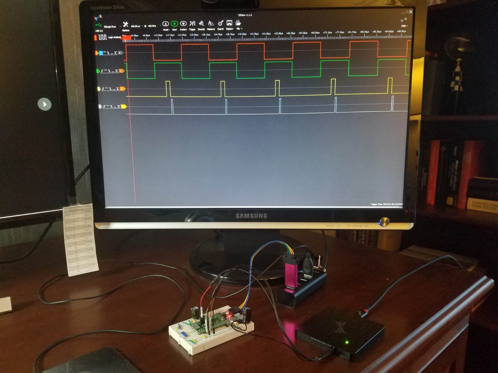
DSView is open source and runs on Windows, macOS and Linux, with nearly 100 protocol decoders. It is not identical to PulseView, and reviewers who know sigrok find the differences annoying, but the decoder breadth is hard to match.
Note that triggering works in buffer mode only. If you want a live streaming view, you lose the trigger.
For whom this analyzer works
Serious Arduino and ESP32 builders who want 16 digital channels, real trigger conditions and a capture that is guaranteed complete. The adjustable threshold makes it the safest pick for 3.3V and mixed-voltage benches.
It is also the natural choice if you want open-source software you can inspect and extend, rather than a closed application.
Where you will feel the limits
There are no analog inputs at this level, so a mixed signal fault on an Arduino power rail still needs another instrument.
The light display mode is far too bright for inspecting small pulses, and some buyers received reduced packages from third-party sellers without the clips or case.
9. Saleae Logic Pro 16 – Best for Full Mixed-Signal Work
Saleae Logic Pro 16 (Red) – Saleae 16-Channel Logic Analyzer – Compatible With Windows, Mac, or Linux – Easy To Use, Ultra-Portable, Saves Time & Frustration
- Highest channel count here with 16 digital/analog inputs
- 500 MS/s digital and 50 MS/s analog sampling
- Software quality and support consistently praised
- Aluminum construction feels premium
- Far beyond what most Arduino projects need
- Heaviest unit at 1.1 pounds
- Same 500 MS/s instability reports as the Logic Pro 8
The Logic Pro 16 doubles the channel count of the Logic Pro 8 while keeping the same 500 MS/s digital and 50 MS/s analog rates, with 16 inputs that each handle digital or analog signals.
Sixteen channels is the number you need when several buses run at once and you refuse to compromise. An ESP32 board with SPI flash, I2C, UART logging and a control signal is exactly that project, and you can capture all of it in one pass instead of rebuilding the probe set three times.
Like its sibling it streams more than 10 billion digital samples into host memory over USB 3.0, with more than 500 million analog samples. The 23-plus decoders and the search and annotation tools are the same ones reviewers praise on the smaller unit.
At 4.8 stars across 35 reviews, buyers at this tier describe it as the strongest unit here for build quality, channel count and software.
For whom this analyzer works
Multi-bus debugging and high pin-count work, especially where analog and digital signals have to be correlated in a single time window. Mixed digital and analog on the same channel set is the feature that cannot be added later.
Where you will feel the limits
It weighs 1.1 pounds and measures 10.9 by 7.4 by 3 inches, so it is the least portable unit here. That matters if you expected a bag-friendly tool.
The same 500 MS/s instability reports appear as on the Logic Pro 8, and for most Arduino projects this is far more instrument than the problem needs.
Frequently Asked Questions
What is the best logic analyzer for Arduino projects?
The HiLetgo 8-channel 24MHz unit is the best all-round choice for Arduino work: it decodes I2C, SPI and UART reliably, handles 5V and 3.3V buses, and runs with free sigrok PulseView software. Step up to the InnoMaker LA1010 for 16 channels and 30-plus decoders, or to the DSLogic Plus when you need real triggering and 400MHz buffer-mode capture.
Can I use an Arduino as a logic analyzer?
Yes. Upload a sketch that speaks the SUMP protocol and PulseView will connect to it the same way it connects to a USB analyzer. Using the analog comparators and timers on an Uno you get roughly six channels at modest sample rates, which suits slow I2C, UART and interrupt work but not fast SPI. An ESP32 can do the same through its built-in USB-Serial-JTAG peripheral.
What software can I use for a logic analyzer?
PulseView from the sigrok project is free, open source and works with every budget analyzer in this roundup, plus DSView for DSLogic hardware, KingstVIS for the InnoMaker LA1010, and Saleae Logic 2 for Saleae devices. PulseView needs a one-time WinUSB driver swap in Zadig on Windows before the analyzer appears.
When should I use a logic analyzer instead of an oscilloscope?
Use a logic analyzer for digital bus problems: I2C, SPI, UART, JTAG and bit-banged traffic, where it shows many pins at once and decodes the bytes. Use an oscilloscope for analog questions such as rise times, ringing, PWM shape, regulator stability and sensor output voltage. A multimeter tells you the voltage on one pin at one moment.
How many channels do I need for I2C, SPI and UART?
I2C needs two channels, one for SDA and one for SCL. UART needs two, one for TX and one for RX. SPI needs four: MOSI, MISO, SCK and chip select. SDIO and QSPI need six, and a parallel LCD can need eight to sixteen. An eight-channel analyzer covers everything except wide parallel buses.
Can a logic analyzer damage a 3.3V Arduino board?
The analyzer itself is unlikely to be the problem if you keep the probe input within its rated range and connect the ground clip to the Arduino GND pin first. A fixed-threshold probe set to 5V logic can read a 3.3V line incorrectly, which leads people to change code that was fine. For 1.8V buses, use an analyzer with an adjustable threshold or place a level shifter between the probe and the target.
Final Verdict
If you read one thing in this roundup, read this: buy the HiLetgo 8-channel 24MHz analyzer. It carries the largest review base of any pick at 589 reviews and a verified 4.5 rating, it decodes every bus an Uno or Nano actually uses, and it runs with free software you will still be using in five years.
Move up to the InnoMaker LA1010 when you need more channels and a decoder library that covers CAN and Modbus. Move up to the DSLogic Plus when you want guaranteed-complete on-board captures and trigger conditions that find the exact bad transaction. The Saleae units are the answer when software quality and mixed analog and digital capture justify the cost.
Whichever you choose, clip the ground to the Arduino GND first, probe SDA and SCL on A4 and A5 for I2C, D11 to D13 plus D10 for SPI, and D0 and D1 for UART. That, plus PulseView and a ten-minute Zadig install, is the whole path from a bus that will not talk to a bus you can read.